Downdraft Table
Why buy it if you can build it? I designed a downdraft table based on the tables from Dynabrade and Sandman. I’m pretty sure Sandman just copied the original Dynabrade table.
I really liked the idea of the filters being on the top of the table. This keeps most of base clean since only filtered air passes through. When it comes time to clean/replace the filters none of the dust falls out either.
I ordered 5”x2” fully locking casters, 25”x25”x2” MERV13 filters, gas struts, a 3/4hp 13” blower, 3/4” birch plywood, and 1x4 maple.
First step was cutting down all of the pieces to size.
Here’s dad laying out the pieces that will make up the lid.
We cut slots in the side pieces using the tracksaw track and router. This worked really well.
Here’s a detailed view of our slots and pre-drilled and countersunk holes for the stainless #10 screws.
We spliced the ends of the bottom of the lid. This gives extra torsional rigidity to the lid.
The lid was then cut for biscuits, and matching cuts were made in the maple frame.
I installed threaded brass inserts and t-nuts for the piano hinge.
Here is the top during our practice clamp up. We wanted to make sure we had everything staged before applying the glide (Titebond III)
Here are the cutouts for the Magnehelic and the start/stop switch. There was a little tear out with the jig saw that will be sanded and filled before painting.
After we had all of the sides cut, sanded and biscuit, we glued up the five sides of the box. The diagonal clamp on the top was to pull the box perfectly square.
After the box had been completely assembled we flipped it over to install the casters.
Here the box and the lid are joined with the full length stainless steel piano hinge.
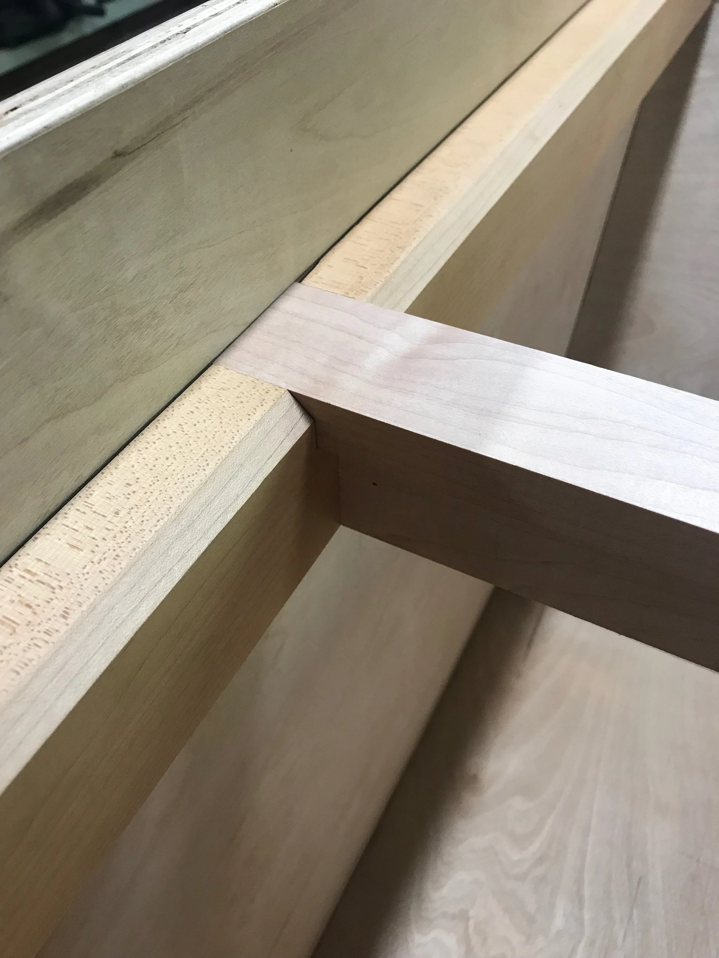
To create a ledge for the filters to sit on, we used 2x4 and 1x4 maple. The thicker stringers keep the sides from flexing. The center piece will be removable to allow for the installation of the blower.
We chamfered the edge so as not to block the filter element. The filter frame is only 3/4” thick, and we wanted to expose as much filter element as possible.
The maple is so nice to work with!
Here is another view of the assembled box with the lid up. Notice the cutouts for the gas strut brackets on the lid. All of the screws are stainless.
This is the cutout for the blower exhaust.
The blower outlet will have a pieces of stainless steel mesh to keep debris and small critters from getting up in the blades. Instead of leaving the edges exposed, I made a bezel to conceal them.
The working surface is made from a piece of 1/4” thick ABS plastic. We worked out the hole pattern after studying a few photos of the Dynabrade and Sandman tables online. The higher density of holes around the edges minimized the amount of dust that can escape over the edge of the table. Dad drilled all 400+ holes with a 3/4” carbide hole saw. After I deburred each hole top and bottom.
I briefly assembled the top and installed the blower to get a rough amperage draw. This is a three speed blower and I found that running on anything other than low draws too much current.
Low speed draws about 14A, medium is 16.5A, and high is 19A. I am planning on plugging the downdraft table into a 15A circuit, so I really need to be under 15A to avoid tripping the breaker.
I have another simultaneous project going on right now, the DoAll bandsaw. I really like the color of paint I’m using for that project, so I decided to go with that for the base. The color is Sherwin Williams Attitude Grey. I opted for a semi-gloss latex to hide some of the minor imperfections, but also allow for easy cleaning.
I used a satin polyurethane on the lid. Here you can see the gas struts installed, and the 3/4” EDPM seal.
I also installed the 3/4”x1/8” EPDM seal where the filters will sit. This is one area I noticed that the dust gets by the production models. I’m hoping this will seal everything up. You can see the wiring and plumbing for the magnehelic. The magnehelic compares the pressure inside the box to outside the box, indicating the pressure drop across the filters. New filters have about 1/4inH2O of pressure drop, and require changing when the pressure drop reaches 1inH2O.
The main power cord is sealed with a grommet and attached to the box for strain relief.
I sealed the outside of the box/cord with a plastic trim plug.
Next, I wired the switch. I stripped and labeled all of the wires and crimped ring terminals. In the future if I want to run the blower on med or high, all I have to do is disconnect one wire, and reconnect another.
Detailed view of the EPDM foam.
All of the production models have aluminum angle edge guards to protect the box from damage. Always wanting to improve upon a design, I made my own edge guards out of Grade-2 Titanium and bonded them on with an Acrylic Adhesive.
Here’s the finished product! Click on the pic above to install the filters and close the lid!
More finish shots. Enjoy!


